NEC NC2500S Bedienungsanleitung
Stöbern Sie online oder laden Sie Bedienungsanleitung nach Datenprojektoren NEC NC2500S herunter. NEC NC2500S User's Manual Benutzerhandbuch
- Seite / 64
- Inhaltsverzeichnis
- LESEZEICHEN
- User’s Manual 1
- Important Information 2
- Table of Contents 9
- What’s in the Box? and 10
- Projector Parts 10
- available 11
- 1-3-1. Front of the projector 14
- 1-3-2. Rear of the projector 15
- 1-3-4. Connection terminals 17
- 1-3-5. Control panel 18
- Remote control 21
- Reception unit on projector 21
- (Top view of the projector) 21
- Installation and 23
- Connection 23
- Ethernet cable 25
- Projection of Images 26
- (Basic Operation) 26
- Remove the lens cap 27
- Using Menus 33
- 4. Using Menus 34
- Maintenance of Your 44
- Projector 44
- Appendix 45
- 6. Appendix 46
- Ver.3 06/06 63
- 7N8P6673 64
Inhaltsverzeichnis
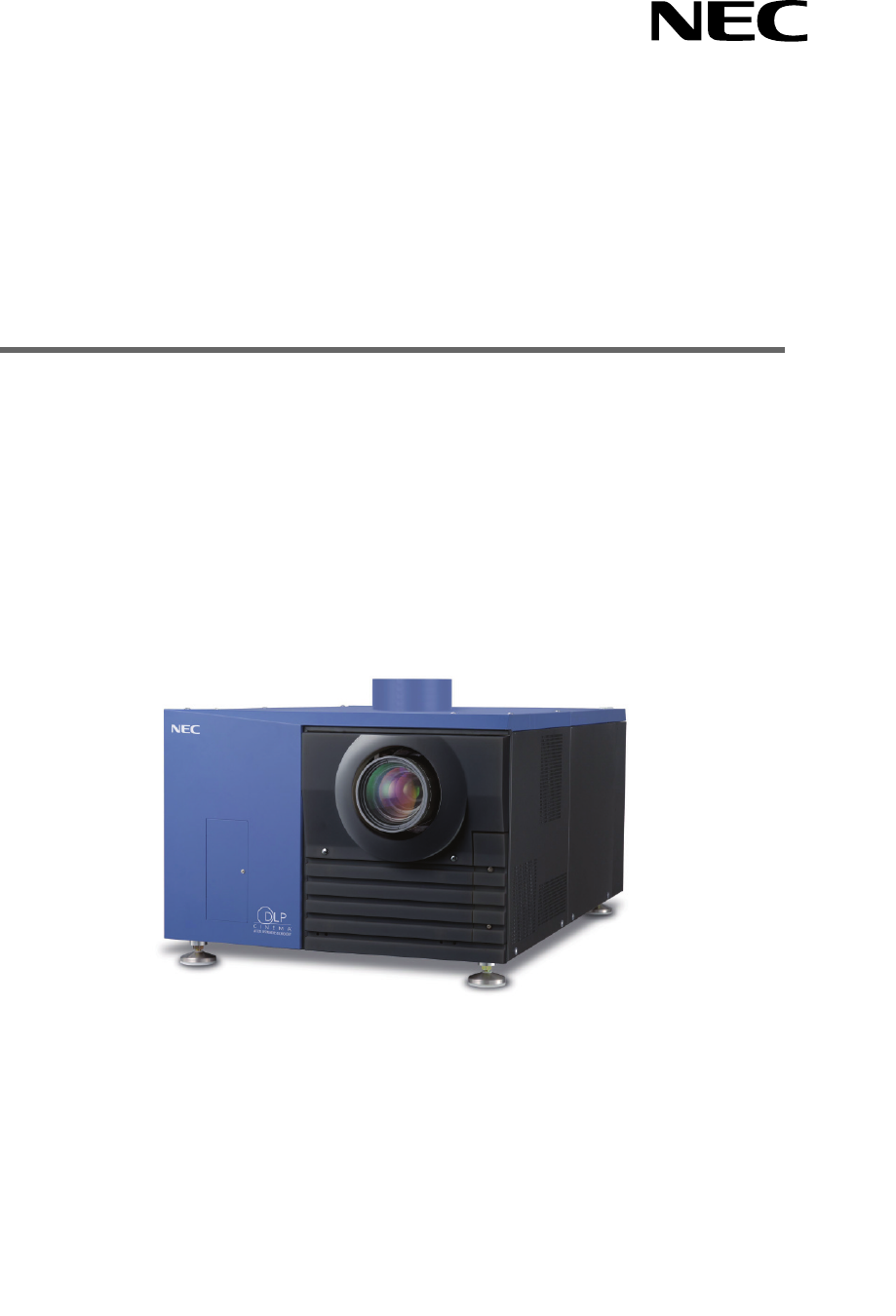
NC2500SUser’s ManualDLP Cinema® ProjectorNEC Viewtechnology, Ltd.
21.What’s in the Box? andthe Names of theProjector Parts1-1. Features• DLP Cinema® dedicated projector that supports large screen needsNEC has applied
31. What’s in the Box? and the Names of the Projector Parts• DMD Face Dust Protection StructureA dust contral shield is arranged between each DMD chip
1. What’s in the Box? and the Names of the Projector Parts41-2. What’s in the Box?Check the content of the accessories. The accessories are packed int
51. What’s in the Box? and the Names of the Projector PartsContents of lamp power supply unit Box Lamp Power Supply (With power cord) Ferrite clamp
1. What’s in the Box? and the Names of the Projector Parts61-3. Names of the Projector Parts1-3-1. Front of the projector123567481091. Air outletConne
71. What’s in the Box? and the Names of the Projector Parts1-3-2. Rear of the projector145321. Air inletAir is taken in here to provide cooling of the
1. What’s in the Box? and the Names of the Projector Parts81-3-3. Lamp power supply unit (LPSU)23541(Rear)61. Air outletThis exhausts heat from the la
91. What’s in the Box? and the Names of the Projector Parts1-3-4. Connection terminalsSDI-ASDI-BDVI-ADVI-BGP I/OLAN-ALAN-BREMOTEINRS-232CPC CARDUSBCIN
1. What’s in the Box? and the Names of the Projector Parts101-3-5. Control panelMMSSTATUS12 8 910 11 19 2012 13 1816 17 5 6 71514341. Remote control l
111. What’s in the Box? and the Names of the Projector Parts9. 1 to 8 buttonsPress the 1 to 8 buttons while depressing the CTL (MACRO) button to selec
WARNINGTO PREVENT FIRE OR SHOCK HAZARDS, DO NOTEXPOSE THIS UNIT TO RAIN OR MOISTURE. ALSO DONOT USE THIS UNIT’S POLARIZED PLUG WITH ANEXTENSION CORD R
1. What’s in the Box? and the Names of the Projector Parts121-4. Names on the Remote Control1. POWER ON buttonOperate this button to turn on the power
131. What’s in the Box? and the Names of the Projector Parts11. SELECT buttons• Press the SELECT / button when the menu is displayed, and a men
1. What’s in the Box? and the Names of the Projector Parts14Using the remote control cableUse the remote control cable when there are objects that int
152-1. Steps for setting up and connectingUse the following steps for setting up your projector:• Step 1Setup the screen and projector. (Contact your
2. Installation and Connection162-2. Connecting the image input terminalsYour projector has four image input terminals, namely, the HDSDI A input term
2. Installation and Connection172-3. Connecting the various control terminalFor control, your projector comes with such ports as the PC control termin
183-1. Steps of projecting images• Step 1Turn on the power to the projector. (See page 19)• Step 2Select the title of input signal. (See page 21)• Ste
193. Projection of Images (Basic Operation)3-2. Turning your projector onThe power to this projector is separated to the power to the projector head a
203. Projection of Images (Basic Operation)4Press the POWER button on the control panel of your projector three seconds or longer.Your projector is tu
213. Projection of Images (Basic Operation)3-3. Selecting the title of input signalThis projector allows you to select pre-registered signals using th
Fire and Shock Precautions1. Ensure that there is sufficient ventilation and that ventsare unobstructed to prevent potentially dangerousconcentrations
223. Projection of Images (Basic Operation)3-4. Adjusting the position and the size of projected screen3-4-1. Displaying the test pattern1Press the TE
233. Projection of Images (Basic Operation)3-4-3. Fine adjustment of the size of the projected screen (Zoom)1Press the ZOOM +/- buttons while depressi
243. Projection of Images (Basic Operation)3-5. Turning your projector off1Press the POWER button on the projector control panel for three seconds or
254-1. Basic operation with adjustment menusTo adjust the projector, display the menu on the LCD screen of the projector control panel.4-1-1. Screen d
264. Using MenusWhen not displaying menus, the following screen is normally displayed.When in standbyWhen the projector is in a standby state (the mai
274. Using Menus3Press the [MENU CTL] DOWN button.The submenu “Lamp” of “Information” is displayed.The menu item can be selected by pressing the ENTER
284. Using Menus4-1-3. How to enter alphanumeric charactersAlphanumeric characters are entered for items, such as the title of input signal.With this
294. Using Menus4-2. Table of adjustment menusMenus in parentheses are menus for our service personnel. Normally, these menus cannot be used.Main menu
304. Using Menus4-3. Title Select4-3-1. Title select (Title Memory)Selects the title of the signal to be projected.You can register up to 100 titles.
314. Using Menus4-4. ConfigurationPlease request your dealer/distributor to perform the settings.4-4-1. Lamp SetupAdjustAdjusts the lamp output (brigh
Précaution: lire attentivement ce manuel avant d’utiliser leNC2500S et le conserver à portée de main pour futureréférence.AVERTISSEMENTPOUR EVITER UN
324. Using Menus4-6. InformationDisplays the hours of lamp bulb use, the version information and error codes.4-6-1. LampDisplays information relating
334. Using Menus4-6-3. UsageDisplays the hours of projector head, lamp, and lamp house usage, and warning display time of the lamp bulb.ProjectorBulbL
344. Using Menus4-6-5. VersionDisplays the versions of the projector head, and the multi-media switcher (MMS) (optional).SystemDisplays the version in
354. Using Menus4-6-6. IP AddressDisplays the IP address set in the projector head.SystemCinemaDisplays the IP address set for the projector head (Sys
36NOTEPlease request your dealer to perform lamp replacement, filter replacement and cleaning of the projectorinside.5-1. Cleaning the CabinetBe sure
376-1. TroubleshootingBefore asking for repair, please check your connection, settings and operation once again. If the trouble cannot be corrected,pl
386. AppendixProblemThe projector cannot be operated with the remote control. The STATUS indicator blinks in red. An error code is displayed. Check th
396. Appendix6-2-3. MMS STATUS indicatorIndicator condition Off Blinking light Steady lightProjector condition Multi-media switcher (MMS) not in use.
406. Appendix6-3. Error code listPlease inquire your dealer/distributor about action to be taken for each error code.Description is omitted for error
416. AppendixError code65666768697071909192123125130131132150-158160161170171172173Error message PB FPGA Reg R/W FailPB Serial-ID Chip FailPB CLUT-SRA
2. Empêcher tous cocps étrangers tels que des attachestrombones ou des morceaux de papier de tomber àl’intérieur du projecteur. Ne pas essayer de récu
426. Appendix6-4. Operation using an HTTP browser6-4-1. OverviewThe use of HTTP server functions will allow control of the projector from a web browse
436. Appendix6-4-4. Structure of the HTTP server PowerTitle ListBasic ControlLensMuteProjector StatusControls the power to your projector. • On: Turn
446. Appendix6-5. Outline Drawing6-5-1. Projector head outline drawing359503110098510950.5600146700Units: mm
456. Appendix6-5-2. Lamp power supply unit outline drawing14 1439759656812 1229551471Units: mm
466. Appendix6-6. SpecificationsModel No.Projection methodPanel resolutionLamp typeScreen sizesContrast ratio Lens adjustment functionSignal input ter
476. AppendixCaracteristiques techniquesNuméro du modèleMode de projectionRésolution du panneauType de lampeTailles d'écranRapport de contrasteFo
486. AppendixTechnische DatenModellnummerProjektionsverfahrenBildflächenauflösungLampentypBildschirmgrößenKontrastverhältnisLinsenbewegungSignaleingan
496. Appendix6-7. Pin Assignment and Functions of Terminal6-7-1. PC CONTROL connector (D-Sub 9 pin)This is an RS-232C interface for controlling the pr
506. Appendix6-7-2. Remote control input connector (REMOTE IN) (Stereo mini)Connected with the projector’s remote control the accessory remote cable.W
516. Appendix6-7-4. External control connector (GP I/O) (D-Sub 37 pin)It is possible to control the projector with an external device and to control t
Maschinenlärminformations-Verordnung – 3. GPSGV,Der höchste Schalldruckpegel beträgt 70 dB(A) oder wenigergemäß EN ISO 7779.WARNUNGZUR VERMEIDUNG VON
526. AppendixInput ConnectorGP I/O Connector Inside ProjectorPhoto-couplerForward direction voltage: 1.1V (@5mA)Resist = 390 ΩExt_GPIN_PPin No.: 12345
536. Appendix6-7-5. SDI-A, SDI-B (HD-SDI input connector) (BNC)This is a signal input connector (SMPTE 292/HDSDI) for CINEMA.The SMPTE 292/HD-SDI tran
546. Appendix6-8. Related products listProduct nameLensAnamorphic lensAnamorphic lens motorized turretLamp house module (excluding lamp)LampPower cord
© NEC Viewtechnology. Ltd. 2005-2006 Printed in JapanVer.3 06/06
7N8P6673NC2500S User’s ManualPrinted on recycled paper
Vorsichtsmasnahmen zur Vermeidung von Brändenund elektrischen Schlägen1. Sorgen Sie für ausreichende Belüuftung und stellen Sieaußerdem sicher, dass d
G-3Bei Fragen, die sich aus unklaren Punkten oderReparaturarbeiten ergebenBei Fragen, die sich aus unklaren Punkten, Fehlfunktionen oderReparaturarbei
1Table of ContentsTable of Contents ................... 11.What’s in the Box? and the Names o
Verwandte Produkte und Handbücher für Datenprojektoren NEC NC2500S
 (79 Seiten)
(110 Seiten)
(156 Seiten)
(2 Seiten)
(99 Seiten)
(55 Seiten)
(2 Seiten)
(105 Seiten)
(74 Seiten)
(79 Seiten)
(110 Seiten)
(156 Seiten)
(2 Seiten)
(99 Seiten)
(55 Seiten)
(2 Seiten)
(105 Seiten)
(74 Seiten)


 (6 Seiten) (133 Seiten)
(97 Seiten)
(6 Seiten) (133 Seiten)
(97 Seiten)
 (79 Seiten)
(56 Seiten)
(79 Seiten)
(56 Seiten)
© 2020, manymanuals.de. Alle Rechte vorbehalten. | 0.117 s |
 Manymanuals.com
 Manymanuals.de
 Manymanuals.fr
 Manymanuals.it
 Manymanuals.pl
 Manymanuals.cz
 Manymanuals.es
 Manymanuals-pt.com
Kommentare zu diesen Handbüchern